
MEDIUM VOLTAGE · SECONDARY DISTRIBUTION
LHSUniSec Air
Medium voltage.
A breath of change.
Air insulation. Vacuum interruption. SF6-free.
Eleven unit families to build secondary distribution around your plant’s requirements.
YOUR PLANT IS THE STARTING POINT
ENERGY EVOLVES.
SO DOES YOUR SWITCHGEAR.
LHS UniSec Air combines incoming supply, protection, metering and isolation: different units combine to build the distribution system you need.
01 / SPECIFICATIONS
EVERY RATING.
ITS CONFIGURATION.
12, 17.5 or 24 kV. Read the ratings by voltage, then explore each unit.
Switchgear electrical ratings
Scroll to view all columns ↔| Quantity | Unit | 12 kV | 17,5 kV | 24 kV |
|---|---|---|---|---|
| Rated voltage | kV | 12 | 17,5 | 24 |
| Test voltage at 50 Hz for 1 min | kV | 28 | 38 | 50 |
| Impulse withstand voltage | kV | 75 | 95 | 125 |
| Rated frequency | Hz | 50 | 50 | 50 |
| Main busbar rated current | A | 630/1250 | 630/1250 | 630/1250 |
| Rated short-time withstand current | kA (3 s) | 16/20/25 | 16/20/25 | 16/20 |
| Peak current | kAp | 40/50/62,5 | 40/50/62,5 | 40/50 |
| Internal arc withstand (up to IAC AFLR) | kA (1 s) | 16/20/25 | 16/20/25 | 16/20 |
For your project. Ratings are configuration-specific. The catalogue introduction associates 1,250 A and 25 kA with LSC2B units; the DRC and DRS sheets also list these values. ICEL must confirm the applicable combination for the project. At 24 kV the general table lists a maximum of 20 kA.
The switchgear and its main devices comply with the following standards:
Reference standards
Scroll to view all columns ↔| Standard | Scope |
|---|---|
| IEC 62271-1 | Common specifications for high-voltage switchgear and controlgear |
| IEC/EN 62271-200 | AC metal-enclosed switchgear |
| IEC 62271-100 | AC circuit-breakers |
| IEC 62271-102 | AC disconnectors and earthing switches |
| IEC 62271-103 | AC switches |
| IEC 62271-105 | Switch-fuse combinations |
| IEC 62271-106 | AC contactors |
| IEC 60071-2 | Insulation coordination |
| IEC 60529 | Degrees of protection provided by enclosures (IP code) |
| IEC 61869-2 | Current transformers |
| IEC 61869-3 | Inductive voltage transformers |
| IEC 61869-10 | Low-power passive current transformers (sensors) |
| IEC 61869-11 | Low-power passive voltage transformers (sensors) |
| IEC 62262 | Resistance to mechanical impacts (IK07) |
Classifications according to IEC 62271-200:
Loss of service continuity: LSC1, LSC2, LSC2A and LSC2B.
Partitions: PI for switch-disconnector units, disconnector units and 24 kV withdrawable circuit-breaker units; PM for withdrawable circuit-breaker units up to 17,5 kV.
Service conditions
Scroll to view all columns ↔| Parameter | Value |
|---|---|
| Storage temperature | –5 °C … +70 °C |
| Ambient operating temperature | –5 °C … +40 °C |
| Maximum relative humidity (non-condensing) | 95 % |
| Minimum relative humidity (non-condensing) | 5 % |
| Altitude | ≤ 1000 m above sea level |
Degrees of protection
Scroll to view all columns ↔| Configuration | IP rating |
|---|---|
| Standard – enclosure (excluding the operating area) | IP3X |
| Standard – separation between compartments | IP2X |
| Optional for LSC2B units – enclosure and mechanical operating mechanisms | IP31 / IP32 / IP4X / IP41 / IP42 |
02 / EXPLORE THE UNITS
A PRECISE FUNCTION.
FOR EVERY REQUIREMENT.
Select a unit code. Compare applications, dimensions, ratings and accessories.
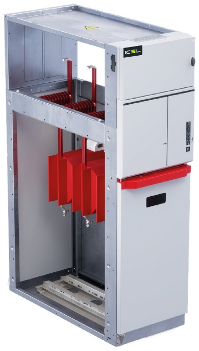
Direct cable incoming
Unit for connecting cables directly to the busbars. The lower door can only be opened with a tool and has an inspection window. In the 500 mm version, an earthing switch with full making capacity can be installed to earth the busbars or incoming cable; CTs, combined sensors or VTs can be fitted. Also available without cable entry, for voltage measurement and busbar earthing.
Discuss this unit ↗DRC · technical data
Scroll to view all columns ↔| Width [mm] | Weight H 1700 [kg] | Weight H 2000 [kg] | Un [kV] | Ir [A] | Ik [kA] |
|---|---|---|---|---|---|
| 500 | 135 | 145 | 12 / 17,5 | 630 / 1250 | 16 / 20 / 25 (3 s) |
| 500 | 135 | 145 | 24 | 630 / 1250 | 16 / 20 (3 s) |
Standard equipment and accessories
DRC · equipment and accessories
Scroll to view all columns ↔| Standard equipment | Optional accessories |
|---|---|
| Unit | |
| Integrated standard auxiliary-circuit compartment | Auxiliary cable duct |
| Bottom plate | Toroidal CTs/current sensors |
| Earth connections | Anti-condensation heater |
| Earthing points | — |
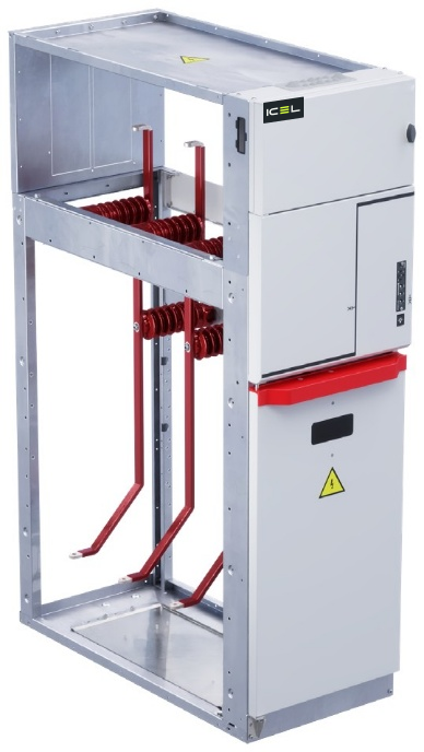
Riser with metering
Riser unit installed alongside a bus coupler with circuit-breaker or disconnector. The 500 mm version can accommodate three CTs and three VTs. The door can only be opened with a tool and has an inspection window. The 500 mm-wide, 2000 mm-high version can be coupled to WBC and WBS units.
Discuss this unit ↗DRS · technical data
Scroll to view all columns ↔| Width [mm] | Weight H 1700 [kg] | Weight H 2000 [kg] | Un [kV] | Ir [A] | Ik [kA] |
|---|---|---|---|---|---|
| 500 | 135 | 145 | 12 / 17,5 | 630 / 1250 | 16 / 20 / 25 (3 s) |
| 500 | 135 | 145 | 24 | 630 / 1250 | 16 / 20 (3 s) |
Standard equipment and accessories
DRS · equipment and accessories
Scroll to view all columns ↔| Standard equipment | Optional accessories |
|---|---|
| Unit | |
| Integrated standard auxiliary-circuit compartment | Auxiliary cable duct |
| Bottom plate | DIN CTs, combined sensors |
| Earth connections | Phase-to-earth or phase-to-phase DIN VTs |
| — | Anti-condensation heater |
| — | Internal lighting |
| — | Enlarged LV compartment |
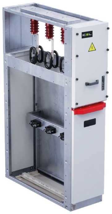
Lateral cable riser with front access
Lateral cable riser, which can be coupled to any LSC2A unit, with earthing points for portable earthing devices. The door can only be opened with a tool and has an inspection window.
Discuss this unit ↗DLR · technical data
Scroll to view all columns ↔| Width [mm] | Weight H 1700 [kg] | Un [kV] | Ir [A] | Ik [kA] |
|---|---|---|---|---|
| 375 | 135 | 12 / 17,5 / 24 | 630 | 16 (3 s) |
Standard equipment and accessories
DLR · equipment and accessories
Scroll to view all columns ↔| Standard equipment | Optional accessories |
|---|---|
| Unit | |
| Bottom plate | Auxiliary cable duct |
| Earthing points | Toroidal current sensors |
| — | Anti-condensation heater |
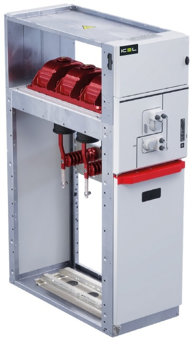
Incoming / outgoing with switch-disconnector
Unit used as an incoming, ring or branch feeder. The three-position switch-disconnector (closed – open – earthed) prevents incorrect operations by design. The cable compartment is accessible only with the device in the earthed position; cable terminations can be inspected through the front window.
Discuss this unit ↗SDC · technical data
Scroll to view all columns ↔| Width [mm] | Weight H 1700 [kg] | Weight H 2000 [kg] | Un [kV] | Ir [A] | Ik [kA] |
|---|---|---|---|---|---|
| 500 | 170 | 180 | 12 / 17,5 / 24 | 630 | 16 (3 s) / 20 (3 s) |
Standard equipment and accessories
SDC · equipment and accessories
Scroll to view all columns ↔| Standard equipment | Optional accessories |
|---|---|
| GSec Air switching device | |
| 3-position switch-disconnector | 4 line – earth indication contacts |
| Mechanical operating mechanism with position indicators | Analogue pressure gauge with alarm contacts |
| Pressure switch | Motor-operated mechanism |
| — | Opening release |
| — | Closing release |
| — | Line/earth blocking magnet |
| — | Key interlocks |
| — | Padlocks |
| Unit | |
| Integrated standard auxiliary-circuit compartment | DIN CTs, combined sensors or toroidal CTs |
| Mechanical interlocks | Current sensors |
| Busbars | Auxiliary cable duct |
| Cable-compartment floor | Anti-condensation heater |
| Earth connections | Internal lighting |
| Voltage-presence indicator | Fault indicator |
| — | Surge arresters |
| — | Terminals for parallel cables |
| — | Terminal blocks |
| — | Enlarged LV compartment |
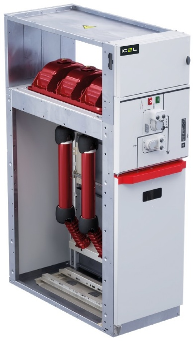
Transformer protection with switch-disconnector and fuses
Unit dedicated to transformer protection. The three-position switch-disconnector, with a double-spring operating mechanism and automatic opening when a fuse operates, earths the upstream side of the fuses; a separate earthing switch (EF 230) acts on the downstream side. The cable compartment is accessible only in the earthed position; terminations can be inspected through the front window.
Discuss this unit ↗SFC · technical data
Scroll to view all columns ↔| Width [mm] | Weight H 1700 [kg] | Weight H 2000 [kg] | Un [kV] | Ik [kA] | Downstream ES Ik (1) | Fuses [A] |
|---|---|---|---|---|---|---|
| 500 | 175 | 185 | 12 / 17,5 / 24 | 16 (3 s) / 20 (3 s) | 5 kAp | up to 100 |
Standard equipment and accessories
SFC · equipment and accessories
Scroll to view all columns ↔| Standard equipment | Optional accessories |
|---|---|
| GSec Air switching device | |
| 3-position switch-disconnector | 4 line – earth indication contacts |
| Mechanical operating mechanism with position indicators | Analogue pressure gauge with alarm contacts |
| Pressure switch | Motor-operated mechanism |
| 1 fuse-operation indication contact | Opening release |
| — | Closing release |
| — | Earth blocking magnet |
| — | Key interlocks |
| — | Padlocks |
| Unit | |
| Integrated standard auxiliary-circuit compartment | Toroidal current sensors |
| Mechanical interlocks | Auxiliary cable duct |
| Fuse-operation indicator | Anti-condensation heater |
| Busbars | Internal lighting |
| Earthing switch downstream of the fuses (EF 230) | DIN fuses |
| Fuse holders | Terminal blocks |
| Cable terminations and bottom plate | Enlarged LV compartment |
| Earth connections | — |
| Voltage-presence indicator | — |
(1) Making capacity of the load-side EF 230 earthing switch (Ik = 2 kA).
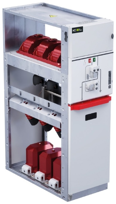
Metering with switch-disconnector and fuses
Unit for voltage measurement. The three-position switch-disconnector opens automatically even when a single fuse operates; it earths the supply side of the fuses, while an optional separate earthing switch acts on the VT side. The voltage transformers are located in the lower part of the unit. The 750 mm version can accommodate both a set of three phase-to-earth VTs and phase-to-phase VTs for revenue metering.
Discuss this unit ↗SFV · technical data
Scroll to view all columns ↔| Width [mm] | Weight H 1700 [kg] | Weight H 2000 [kg] | Un [kV] | Ik [kA] | Fuses [A] |
|---|---|---|---|---|---|
| 500 | 175 | 185 | 12 / 17,5 / 24 | 16 (3 s) / 20 (3 s) | 2 – 6,3 |
| 750 | 200 | 215 | 12 / 17,5 / 24 | 16 (3 s) / 20 (3 s) | 2 – 6,3 |
Standard equipment and accessories
SFV · equipment and accessories
Scroll to view all columns ↔| Standard equipment | Optional accessories |
|---|---|
| GSec Air switching device | |
| 3-position switch-disconnector | 4 line – earth indication contacts |
| Mechanical operating mechanism with position indicators | Analogue pressure gauge with alarm contacts |
| Pressure switch | Motor-operated mechanism |
| 1 fuse-operation indication contact | Opening release |
| — | Closing release |
| — | Earth blocking magnet |
| — | Key interlocks |
| — | Padlocks |
| Unit | |
| Integrated standard auxiliary-circuit compartment | Auxiliary cable duct |
| Mechanical interlocks | Anti-condensation heater |
| Busbars | Internal lighting |
| Fuse holders | DIN fuses |
| DIN VTs (phase-to-earth or phase-to-phase) | Power transformers for auxiliary services |
| Bottom plate | Enlarged LV compartment |
| Earth connections | Blown-fuse indicator |
| Voltage-presence indicator | — |
| VT-side earthing switch | — |
| Fuse-operation indication | — |
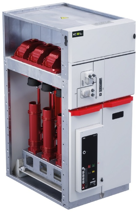
Incoming / outgoing with circuit-breaker and disconnector
Unit for switching and protection of feeders, networks, motors, transformers and capacitor banks. The vacuum circuit-breaker is mounted on a guide and connected to the busbars through a three-position disconnector with earthing, located between the circuit-breaker and busbars. A mechanical key interlock links the disconnector and circuit-breaker; the door is mechanically interlocked with the earthed position. The unit can accommodate CTs, VTs or combined sensors.
Discuss this unit ↗SBC · technical data
Scroll to view all columns ↔| Width [mm] | Weight H 1700 [kg] | Weight H 2000 [kg] | Un [kV] | Ir [A] | Ik [kA] |
|---|---|---|---|---|---|
| 750 | 335 | 355 | 12 / 17,5 / 24 | 630 | 16 (3 s) / 20 (3 s) |
Standard equipment and accessories
SBC · equipment and accessories
Scroll to view all columns ↔| Standard equipment | Optional accessories |
|---|---|
| GSec Air disconnector | |
| Three-position disconnector | 4 line – earth indication contacts |
| Mechanical operating mechanism with position indicator | Analogue pressure gauge with alarm contacts |
| Key interlock with the circuit-breaker | Key interlocks |
| Pressure switch | Padlocks |
| VD4/R-Sec circuit-breaker | |
| Vacuum circuit-breaker | Motor-operated mechanism |
| Mechanical indication and opening and closing pushbuttons | — |
| Unit | |
| Integrated standard auxiliary-circuit compartment | DIN CTs and combined sensors or toroidal CTs and sensors |
| Mechanical interlocks | Phase-to-earth or phase-to-phase DIN VTs without fuses; upstream or downstream DIN CTs |
| Busbars | Current and voltage sensors |
| Cable terminations and bottom plate | Auxiliary cable duct |
| Cable-side earthing switch (ES-230N) | Anti-condensation heater |
| Earth connections | Internal lighting |
| Voltage-presence indicator | Wide range of protection relays |
| — | Surge arresters |
| — | Terminals for parallel cables |
| — | Enlarged LV compartment |
| — | Terminal blocks |
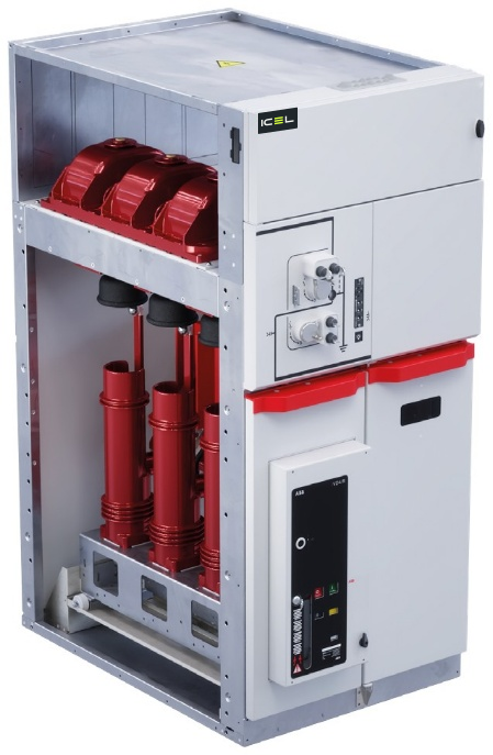
Bus coupler with circuit-breaker and disconnector
Bus-coupler unit installed alongside a riser unit. A three-position disconnector in series with the vacuum circuit-breaker allows busbar isolation; the circuit-breaker is mounted on a guide and connected to the busbars, with a mechanical key interlock between the disconnector and circuit-breaker. It can accommodate DIN CTs or combined sensors.
Discuss this unit ↗SBS · technical data
Scroll to view all columns ↔| Width [mm] | Weight H 1700 [kg] | Weight H 2000 [kg] | Un [kV] | Ir [A] | Ik [kA] |
|---|---|---|---|---|---|
| 750 | 355 | 375 | 12 / 17,5 / 24 | 630 | 16 (3 s) / 20 (3 s) |
Standard equipment and accessories
SBS · equipment and accessories
Scroll to view all columns ↔| Standard equipment | Optional accessories |
|---|---|
| GSec Air disconnector | |
| Three-position disconnector | 4 closed – earth indication contacts |
| Mechanical operating mechanism with position indicator | Analogue pressure gauge with alarm contacts |
| Key interlock with the circuit-breaker | Key interlocks |
| Pressure switch | Padlocks |
| VD4/R-Sec circuit-breaker | |
| Mechanical indication and opening and closing pushbuttons | Motor-operated mechanism |
| Unit | |
| Integrated standard auxiliary-circuit compartment | DIN CTs or combined sensors |
| Mechanical interlocks | Auxiliary cable duct |
| Busbars | Anti-condensation heater |
| ES-230N earthing switch (version with lower-right busbar connection) | Internal lighting |
| Bottom plate | Wide range of protection relays |
| Earth connections | Enlarged LV compartment |
| Voltage-presence indicator | — |
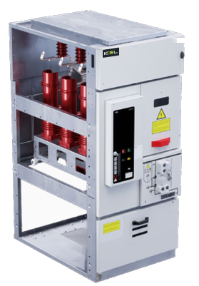
Incoming / outgoing with circuit-breaker and inverted disconnector
The SBR unit allows the disconnector to be opened and earthed while the cable compartment remains in service. It includes a three-position disconnector in series with a vacuum circuit-breaker. The cable compartment is key-interlocked; the circuit-breaker compartment is key-interlocked with the disconnector. The circuit-breaker door is mechanically interlocked with the disconnector’s earthed position.
Discuss this unit ↗SBR · technical data
Scroll to view all columns ↔| Width [mm] | Weight H 1700 [kg] | Weight H 2000 [kg] | Un [kV] | Ir [A] | Ik [kA] |
|---|---|---|---|---|---|
| 750 | 355 | 375 | 12 / 17,5 / 24 | 630 | 16 (3 s) / 20 (3 s) |
Standard equipment and accessories
SBR · equipment and accessories
Scroll to view all columns ↔| Standard equipment | Optional accessories |
|---|---|
| GSec Air disconnector | |
| Three-position disconnector | 4 closed – earth indication contacts |
| Mechanical operating mechanism with position indicator | Analogue pressure gauge with alarm contacts |
| Key interlock with the circuit-breaker | Key interlocks |
| Pressure switch | Padlocks |
| VD4/R-Sec circuit-breaker | |
| Mechanical indication and opening and closing pushbuttons | Motor-operated mechanism |
| Unit | |
| Integrated standard auxiliary-circuit compartment | DIN CTs or combined sensors |
| Mechanical interlocks | Auxiliary cable duct |
| Busbars | Anti-condensation heater |
| ES-230N earthing switch (version with lower-right busbar connection) | Internal lighting |
| Bottom plate | Wide range of protection relays |
| Earth connections | Enlarged LV compartment |
| Voltage-presence indicator | — |
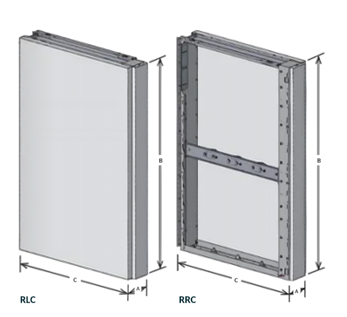
Lateral cable riser
Lateral cable riser, which can be coupled to an SBR compartment, with earthing points for portable earthing devices.
Discuss this unit ↗RLC/RRC · technical data
Scroll to view all columns ↔| Width [mm] | Weight H 1700 [kg] | Un [kV] | Ir [A] | Ik [kA] |
|---|---|---|---|---|
| 200 | 40 | 12 / 17,5 / 24 | 630 | 16 (3 s) |
Standard equipment and accessories
RLC/RRC · equipment and accessories
Scroll to view all columns ↔| Standard equipment | Optional accessories |
|---|---|
| Unit | |
| Earthing points | Toroidal current sensors |
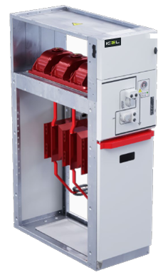
Sectionalising with switch-disconnector
The SDS switch-disconnector unit is used together with a riser unit. Its three-position device – closed, open or earthed – prevents incorrect operations. The earthing system is standard equipment. The 500 mm units can be fitted with current and voltage transformers.
Discuss this unit ↗SDS · technical data
Scroll to view all columns ↔| Width [mm] | Weight H 1700 [kg] | Weight H 2000 [kg] | Un [kV] | Ir [A] | Ik [kA] |
|---|---|---|---|---|---|
| 500 | 170 | 180 | 12 / 17,5 / 24 | 630 | 16 (3 s) / 20 (3 s) |
Standard equipment and accessories
SDS · equipment and accessories
Scroll to view all columns ↔| Standard equipment | Optional accessories |
|---|---|
| GSec Air switching device | |
| 3-position switch-disconnector | 4 line – earth indication contacts |
| Mechanical operating mechanism with position indicators | Analogue pressure gauge with alarm contacts |
| Pressure switch | Motor-operated mechanism |
| — | Opening release |
| — | Closing release |
| — | Line/earth blocking magnet |
| — | Key interlocks |
| — | Padlocks |
| Unit | |
| Integrated standard auxiliary-circuit compartment | DIN CTs, combined sensors or toroidal CTs |
| Mechanical interlocks | Current sensors |
| Busbars | Auxiliary cable duct |
| Cable-compartment floor | Anti-condensation heater |
| Earth connections | Internal lighting |
| Voltage-presence indicator | Fault indicator |
| — | Surge arresters |
| — | Terminals for parallel cables |
| — | Terminal blocks |
| — | Enlarged LV compartment |
Compare all units
The 11 unit families
Scroll to view all columns ↔| Code | Application | Width [mm] | LSC |
|---|---|---|---|
| DRC | Direct cable incoming | 500 | LSC2A |
| DRS | Riser with metering | 500 | LSC2A |
| DLR | Lateral cable riser with front access | 375 | LSC2A |
| SDC | Incoming / outgoing with switch-disconnector | 500 | LSC2A |
| SFC | Transformer protection with switch-disconnector and fuses | 500 | LSC2A |
| SFV | Metering with switch-disconnector and fuses | 500 / 750 | LSC2A |
| SBC | Incoming / outgoing with circuit-breaker and disconnector | 750 | LSC2A |
| SBS | Bus coupler with circuit-breaker and disconnector | 750 | LSC2A |
| SBR | Incoming / outgoing with circuit-breaker and inverted disconnector | 750 | LSC2A |
| RLC/RRC | Lateral cable riser | 200 | LSC2A |
| SDS | Sectionalising with switch-disconnector | 500 | LSC2A |
03 / TECHNOLOGY, UP CLOSE
AIR TO INSULATE.
VACUUM TO INTERRUPT.
Inside GSec Air, separate functions work together. Dry air provides insulation. Vacuum interrupters interrupt the load current.
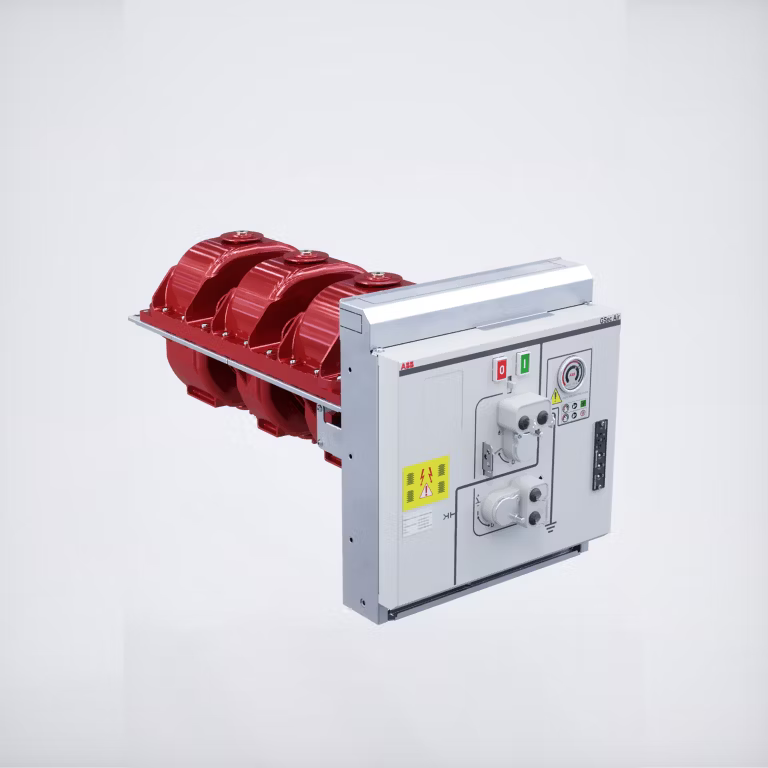
Dry air as the insulating medium.
Sealed GSec Air enclosure.
Operating mechanisms and sequences for the application.
Construction, compartments and access
Each unit is made of pre-galvanized sheet steel and divided into dedicated cable, busbar and apparatus compartments.
LV compartment. Houses auxiliary circuits and instrumentation.
Main busbars. The busbar compartment contains the copper busbar system rated up to 630A, connected to the upper fixed contacts of the switching device.
Interlocks. Standard and optional interlocks ensure the correct operating sequence.
Cable compartment. Front and side access to cables. Up to 2 single-core cables per phase can be connected, depending on voltage, unit width and cross-section.
LV compartment for auxiliary circuits. Each unit has an LV compartment for low-voltage components.
Finish. Pre-galvanised sheet-steel structure. The standard MV compartment door is painted RAL 7035 grey.
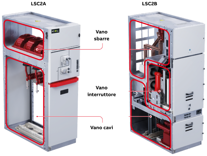
Modularity, service continuity and access
LHS UniSec Air is ICEL’s SF6-free, air-insulated medium-voltage switchgear for secondary distribution up to 24 kV. It complies with IEC standards and Regulation (EU) 2024/573 on fluorinated gases. Its modular design allows switch-disconnector units, removable circuit-breaker units, and front-withdrawable circuit-breaker or contactor units to be combined in the same switchboard, adapting to different installation layouts and extensions of existing installations.
Efficiency: provision for real-time monitoring and predictive maintenance.
Safe and reliable
GSec Air switch-disconnector or disconnector in a sealed enclosure with a volume of less than 25 litres, containing all live parts.
Internal arc classification, with hot gases exhausted inside or outside the room depending on the application.
A wide range of mechanical and electrical interlocks to protect the operator.
LSC2B, LSC2A and LSC2 loss-of-service-continuity categories, selected according to the application and combinable in the same switchboard.
Compliant and sustainable
Dry-air insulation (GWP = 0) and load interruption by dedicated vacuum interrupters.
Switching-device operating mechanisms made from fully recyclable steel.
Easy to install and manage
Compatibility with the previous generation of air-insulated switchgear makes it easier to extend existing installations.
Front and side access to MV cable connections simplifies installation, operation and maintenance.
GSec Air · ratings, operating mechanisms and accessories
Compliant with Regulation (EU) 2024/573. Meets IEC 62271-102, IEC 62271-103 and IEC 62271-105.
Electrical characteristics
GSec Air · electrical ratings
Scroll to view all columns ↔| Quantity | Unit | 12 kV | 17,5 kV | 24 kV |
|---|---|---|---|---|
| Rated voltage | kV | 12 | 17,5 | 24 |
| Power-frequency withstand voltage (50 Hz, 1 min) | ||||
| Phase-to-phase and phase-to-earth | kV | 28 | 38 | 50 |
| Across the isolating distance | kV | 32 | 45 | 60 |
| Impulse withstand voltage (1,2/50 µs) | ||||
| Phase-to-phase and phase-to-earth | kVp | 75 | 95 | 125 |
| Across the isolating distance | kVp | 85 | 110 | 145 |
| Rated frequency | Hz | 50 | 50 | 50 |
| Rated current (40 °C) | A | 630 | 630 | 630 |
| GSec Air/T1 | ||||
| Rated short-time withstand current | kA | 20 (3 s) | 20 (3 s) | 20 (3 s) |
| Making capacity (peak value) (1) | kAp | 50 | 50 | 50 |
| GSec Air/T2 | ||||
| Rated short-time withstand current (2) | kA | 16 (3 s) | 16 (3 s) | 16 (3 s) |
| Making capacity (peak value) (2) | kAp | 31,5 | 31,5 | 31,5 |
| Breaking capacity according to IEC 62271-103 ed. 2021 | ||||
| Mainly active load | A | 630 | 630 | 630 |
| Off-load lines | A | 25 | 25 | 25 |
| Off-load cables | A | 50 | 50 | 50 |
| Closed-loop circuits | A | 630 | 630 | 630 |
(1) For the T2 operating mechanism; for T2F, the maximum value depends on the installed fuse.
Mechanical and electrical performance
Mechanical and electrical performance
Scroll to view all columns ↔| Item | Class |
|---|---|
| Electrical endurance of line contact – T1 mechanism | E3: up to 5 making and 100 breaking operations at rated current |
| Electrical endurance of line contact – T2 mechanism | E1: up to 2 making and 100 breaking operations at rated current |
| Electrical endurance of earth contact – T2 / T2F | E1: up to 2 making operations |
| Electrical endurance of earth contact – T1 | E2: up to 5 making operations / E0 (disconnector version) |
| Mechanical endurance of line contact – T1 (single spring for opening and closing) | M1: 1000 operations |
| Mechanical endurance of line contact – T2 (separate springs) | M1: 1000 operations |
| Mechanical endurance of earth contact – T1 and T2 | M0: 1000 operations |
Operating mechanisms
T1 – operating mechanism without stored energy. Once the dead centre is passed, energy is released and the device closes or opens.
T2 – stored-energy operating mechanism. The springs are charged by lever or motor and held by a retaining system. Closing and opening are then performed locally by pushbutton or remotely by coils.
Operating times
Scroll to view all columns ↔| Time | T1 | T2 |
|---|---|---|
| Spring charging (manual) | Depends on the operator | Depends on the operator |
| Spring charging (motor) | 5–7 s | 5–7 s |
| Contact movement | < 0,3 s | < 0,3 s |
| Total closing time | < 8 s (motor-operated) | < 0,3 s |
| Total opening time | < 8 s (motor-operated) | < 0,3 s |
Accessories
1. Key locks
Key interlocks
Scroll to view all columns ↔| Lock | Configuration | GSec Air/T1 | GSec Air/T2 |
|---|---|---|---|
| Line (1) | 2 free keys: 1 open and 1 closed | ● | — |
| — | 1 free key – open | ● | ● |
| — | 1 free key – closed | ● | — |
| Earth | 2 free keys: 1 open and 1 closed | ● | ● |
| — | 1 free key – open | ● | ● |
| — | 1 free key – closed | ● | ● |
(1) Mandatory for the IB version.
2. Padlock kit (standard). Locks the device in the open, line or earth position; up to three padlocks per device, with a maximum diameter of 6 mm. Padlocks not supplied.
3. Auxiliary contacts. 4 changeover contacts for the line position and 4 for the earth position, usable as NO or NC contacts.
4. Motor operation. Allows remote operation of the line contact; manual lever operation remains possible at all times. With the T2 mechanism, moving the selector from the intermediate position to local or remote automatically charges the springs.
5. MBO4 opening release (GSec Air/T2). Opens the line contact when the coil is energised. Total opening time 300 ms.
6. MBC4 closing release (GSec Air/T2). Closes the line contact when the coil is energised.
Opening and closing coils
Scroll to view all columns ↔| MBO4 / MBC4 | AC (50–60 Hz) | DC |
|---|---|---|
| Supply voltages – low range [V] | 48, 60 | 24, 48, 60 |
| Supply voltages – high range [V] | 110–127, 220–250 | 110–132, 220–250 |
| Inrush power | 200 VA | 200 W |
7. RLE5 electromagnetic lock on the line operating-lever socket (GSec Air/T1). Prevents insertion of the lever when the coil is de-energised. Available with the T1 mechanism only.
8. RLE3 electromagnetic lock on the earth operating-lever socket. Prevents insertion of the earthing lever when the coil is de-energised. Alternative to the earth key lock.
Electromagnetic interlocks
Scroll to view all columns ↔| RLE5 / RLE3 | Value |
|---|---|
| DC supply voltage [V] | 24, 30, 48, 60, 110, 220, 240 |
| Rated power | 250 W |
| Holding power | 5 W |
| Inrush time | 150 ms |
9. Fuse-operation indication. When a fuse operates, a linkage activates an indicator visible from the front. On request, a microswitch with an NO or NC contact provides electrical indication.
10. Pressure monitoring (mandatory). A pressure switch with a volt-free contact is supplied as standard, providing local or remote low-pressure indication when pressure falls below 1,9 bar absolute. Alternatively, an analogue pressure gauge with front indication and remote signalling via dedicated wiring and a terminal block is available on request.
VD4/R-Sec · vacuum circuit-breaker
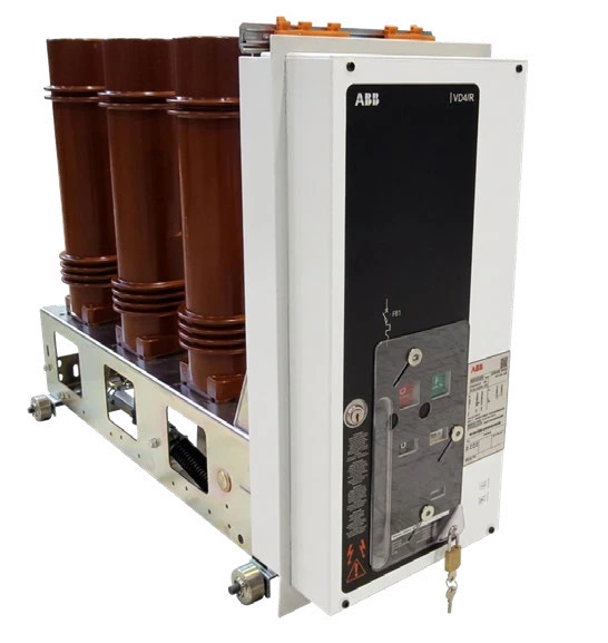
Vacuum circuit-breaker to IEC 62271-100, with a spring operating mechanism (O-0.3 s-CO-15 s-CO).
VD4/R-Sec · ratings
Scroll to view all columns ↔| VD4/R-Sec | Unit | 12 kV | 17,5 kV | 24 kV |
|---|---|---|---|---|
| Rated frequency | Hz | 50 | 50 | 50 |
| Impulse withstand voltage | kV | 75 | 95 | 125 |
| Power-frequency test voltage | kV | 28 | 38 | 50 |
| Rated current | A | 630 | 630 | 630 |
| Breaking capacity | kA | 16×3 s / 20×3 s | 16×3 s / 20×3 s | 16×3 s / 20×3 s |
| Making capacity | kA | 30/40/50 | 30/40/50 | 30/40/50 |
| Short-circuit duration | s | 3 | 3 | 3 |
| Pole pitch | mm | 230 | 230 | 230 |
Standard equipment: closing and opening pushbuttons, operation counter, spring-status indicator and manual charging lever. Kit 1: five NO/NC auxiliary contacts (Un = 24…250 V AC-DC). Kit 2: opening release for remote operation. Kit 3: key lock in the open position, with different or identical keys.
Accessories: spring-charging motor (MAS), closing release (MBC), additional opening release (MBO2), undervoltage release (MBU).
For your project. Table names and values are reproduced from the catalogue. Breaking/making ratings expressed together with a duration, and incomplete footnote references, require confirmation in the project technical documentation.
Earthing switches
In units requiring a separate cable-side earthing switch, different models are used depending on the application.
Earthing switches · applications
Scroll to view all columns ↔| Unit | ES-230N | EF 230 |
|---|---|---|
| SFC | — | ● |
| SFV | — | ● |
| SBC | ● | — |
| SBS | ● | — |
| DRC | ● | — |
Earthing switches · ratings
Scroll to view all columns ↔| Characteristic | ES-230N | EF 230 |
|---|---|---|
| Rated voltage | 24 kV | 24 kV |
| Making capacity | 20 kA × 3 s | 2 kA × 1 s |
| Mechanical endurance | M0 – 1000 | M0 – 1000 |
CEF and CEF-VT fuses · selection tables
In the SFC unit, the switch-disconnector is connected in series with three current-limiting fuses, one per phase. The fuse protects the MV side of the transformer, while overload protection is normally provided on the LV side. Selection must balance two opposing requirements:
withstand the no-load inrush current without deterioration; this can exceed 10 times the rated current, with the maximum value occurring when closing at the voltage zero crossing;
operate quickly for faults in the LV winding and in the section up to the secondary-side circuit-breaker: oversized fuses should therefore be avoided. Good practice is to check the operating time on the fuse time-current curve at the short-circuit current at the secondary terminals.
The table gives the fuse rated current as a function of transformer voltage and power, for current transfer compliant with IEC 60282-1.
CEF fuse selection for transformer protection (SFC unit) – fuse rated current [A]
CEF fuse selection · rated current [A]
Scroll to view all columns ↔Blank cells in the fuse-voltage column are reproduced as supplied; they do not define independent ratings. Transformer powers are in kVA.
| Transformer U [kV] | Load | 25 kVA | 50 kVA | 75 kVA | 100 kVA | 125 kVA | 160 kVA | 200 kVA | 250 kVA | 315 kVA | 400 kVA | 500 kVA | 630 kVA | 800 kVA | 1000 kVA | 1250 kVA | 1600 kVA | 2000 kVA | 2500 kVA | Fuse U [kV] |
|---|---|---|---|---|---|---|---|---|---|---|---|---|---|---|---|---|---|---|---|---|
| 3 | 120% | 10 | 20 | 25 | 31,5 | 40 | 50 | 50 | 63 | 100 | - | - | - | - | - | - | - | - | - | 3/7,2 |
| — | 150% | 16 | 25 | 25 | 40 | 40 | 50 | 63 | 80 | 100 | - | - | - | - | - | - | - | - | - | — |
| 5 | 120% | 10 | 16 | 20 | 20 | 25 | 31,5 | 31,5 | 50 | 50 | 63 | 100 | 100 | - | - | - | - | - | - | — |
| — | 150% | 10 | 16 | 25 | 25 | 25 | 40 | 40 | 50 | 63 | 80 | 100 | - | - | - | - | - | - | - | — |
| 6 | 120% | 6,3 | 10 | 16 | 20 | 20 | 25 | 31,5 | 40 | 50 | 50 | 63 | 100 | 100 | - | - | - | - | - | — |
| — | 150% | 6,3 | 16 | 16 | 25 | 25 | 25 | 40 | 40 | 50 | 63 | 80 | 100 | - | - | - | - | - | - | — |
| 10 | 120% | 4* | 10 | 10 | 16 | 16 | 20 | 20 | 25 | 31,5 | 31,5 | 50 | 50 | 63 | 80 | 100 | - | - | - | 6/12 |
| — | 150% | 4* | 10 | 16 | 16 | 16 | 20 | 20 | 25 | 31,5 | 40 | 50 | 63 | 80 | 100 | - | - | - | - | — |
| 12 | 120% | 2,5* | 6,3 | 10 | 10 | 16 | 16 | 20 | 20 | 25 | 31,5 | 40 | 50 | 50 | 63 | 80 | 100 | - | - | — |
| — | 150% | 2,5* | 6,3 | 10 | 16 | 16 | 16 | 20 | 20 | 25 | 40 | 40 | 50 | 63 | 80 | 100 | - | - | - | — |
| 15 | 120% | 2,5* | 6,3 | 10 | 10 | 10 | 16 | 16 | 20 | 20 | 25 | 31,5 | 40 | 40 | 50 | 63 | 80 | 100 | - | 10/17,5 |
| — | 150% | 2,5* | 6,3 | 10 | 10 | 16 | 16 | 16 | 20 | 20 | 25 | 40 | 40 | 50 | 63 | 80 | 100 | - | - | — |
| 20 | 120% | - | 4* | 6,3 | 10 | 10 | 10 | 16 | 16 | 20 | 20 | 25 | 31,5 | 31,5 | 40 | 50 | 63 | 80 | - | 10/24 |
| — | 150% | - | 4* | 6,3 | 10 | 10 | 16 | 16 | 16 | 20 | 20 | 25 | 31,5 | 40 | 50 | 63 | 80 | - | - | — |
| 24 | 120% | - | 2,5* | 6,3 | 6,3 | 10 | 10 | 10 | 16 | 16 | 20 | 20 | 25 | 25 | 31,5 | 40 | 50 | 63 | 80 | — |
| — | 150% | - | 2,5* | 6,3 | 6,3 | 10 | 10 | 16 | 16 | 16 | 20 | 20 | 25 | 40 | 40 | 50 | 63 | 80 | - | — |
Headers: transformer rated voltage [kV], transformer load, transformer power [kVA], fuse rated voltage [kV]. (*) Value marked with a note in the fuse manufacturer’s documentation: check each case individually.
CEF-VT fuse selection for VT measurement and protection (SFV unit)
CEF-VT fuses
Scroll to view all columns ↔| Type | Striker | Un [kV] | In [A] | Length [mm] | Ø [mm] | I1 [kA] | I3 [A] | Pn [W] | R0 [mΩ] |
|---|---|---|---|---|---|---|---|---|---|
| CEF-VT | yes | 7,2/12 | 2 | 292 | 53 | 63 | 27 | 7,4 | 1,34 |
| CEF-VT | yes | 7,2/12 | 6,3 | 292 | 53 | 63 | 41 | 18 | 0,33 |
| CEF-VT | yes | 17,5/24 | 6,3 | 292 | 53 | 31,5 | 46 | 35 | 0,60 |
| CEF-VT | yes | 17,5/24 | 6,3 | 442 | 53 | 31,5 | 46 | 35 | 0,60 |
I1 = maximum breaking current; I3 = minimum breaking current; Pn = rated power losses; R0 = cold resistance.
Instrument transformers
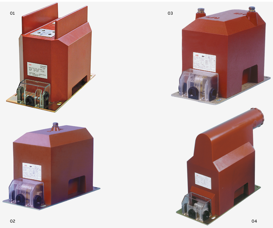
DIN current transformers. Resin-insulated, with one or more cores and burdens and accuracy classes suited to the installation. Compliant with IEC 61869-2, with dimensions according to DIN 42600 narrow type. They can include a capacitive tap for voltage-presence indicators. Reference range: TPU.
DIN voltage transformers. Epoxy-resin-insulated, single- or double-pole, for fixed installation or mounting on a withdrawable plate in withdrawable circuit-breaker units, optionally with a protective MV fuse. Compliant with IEC 61869-3, with DIN 42600 narrow-type dimensions. Reference range: TJC, TDC, TJP (with fuse).
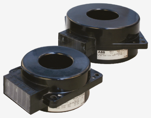
Toroidal current transformers. Resin-insulated for low voltage, closed-core or split-core, for up to two cables per phase; for phase-current measurement or earth-fault detection. Compliant with IEC 61869-2. Much lighter than DIN CTs, they fit around the insulated cable and can be installed close together, providing substantial space and weight savings.
Protection and automation
The LV compartments of LHS UniSec Air units accommodate a wide range of protection relays. Depending on the technical requirements, the following can be used:
Self-powered relay
Protects secondary distribution feeders and transformers against overcurrent, earth faults and overloads, and is ideal as the main protection for distribution transformers. It requires no external power supply: it takes its energy directly from the current transformers. It can also receive trip signals from the transformer, for example in the event of overheating.
Feeder protection
Protects overhead lines and cables against short circuits, overcurrent and earth faults in both primary and secondary distribution, and is also suitable for transformer protection. Several versions are available, progressively adding thermal protection, automatic reclosing for overhead lines, circuit-breaker supervision and fault recording. For more complex protection and control applications, specific devices can be used according to the required functions.
04 / INTERNAL ARC WITHSTAND
THE SWITCHGEAR.
THE ROOM. THE SAFETY.
Base version, filters or a duct. Gas management depends on the switchgear configuration and the installation room.
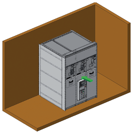
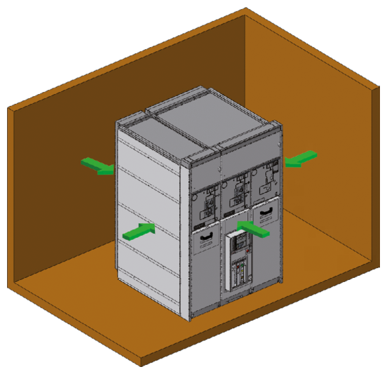
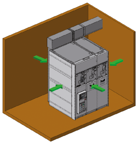
The switchgear has been tested according to IEC 62271-200; internal arc withstand can be provided at the front (F), sides (L) and rear (R).
Classifications and gas exhaust
Scroll to view all columns ↔| Solution | Classification | Gas exhaust | Switchgear installation |
|---|---|---|---|
| Base | IAC AF up to 16 kA 1 s | Into the room | Against a wall, with 100 mm clearance. No access to the rear or sides during operation. |
| Absorber filters | IAC AFLR up to 20 kA 1 s IAC AFLR 25 kA 1 s (LSC2B ≤ 17,5 kV only) | Into the room, after cooling and pressure reduction through the filters | Near a wall or in the centre of the room. Filters mounted on the rear of each unit, with no additional site work. |
| Exhaust duct | IAC AFLR up to 20 kA 1 s IAC AFLR 25 kA 1 s (LSC2B ≤ 17,5 kV only) | Outside the room or into the trench below | Near a wall or in the centre of the room. Standard 1 m extension, with outlet to the right, left, rear or top. |
For longer exhaust ducts, contact the ICEL technical department.
05 / FOR THE DESIGNER
FROM RATINGS.
TO REAL SPACE.
Dimensions, weights, clearances and connections. The catalogue information you need to prepare your project.
The dimensions shown refer to standard units, not special configurations. Final values are given in the project drawings.
LSC2A envelope diagram, not to scale. +110 mm at the front for units with a side-mounted circuit-breaker. IAC AFLR 20 kA with filters: H 2000 mm only. The original drawings below include construction details.
LSC2A overall dimensions
Scroll to view all columns ↔| Configuration | Height [mm] | Depth [mm] | Additional dimensions [mm] |
|---|---|---|---|
| LSC2A – IAC A-F 16 kA 1 s | 1700 / 2000 | 1070 | +110 at the front for units with a lateral circuit-breaker |
| LSC2A – IAC A-FLR 16 kA 1 s with filters | 1700 / 2000 | 1070 | +140 for rear filters; +110 at the front for units with a lateral circuit-breaker |
| LSC2A – IAC A-FLR 20 kA 1 s with filters | 2000 | 1070 | +140 for rear filters; +110 at the front for units with a lateral circuit-breaker |
Original drawings · dimensions and LV compartments
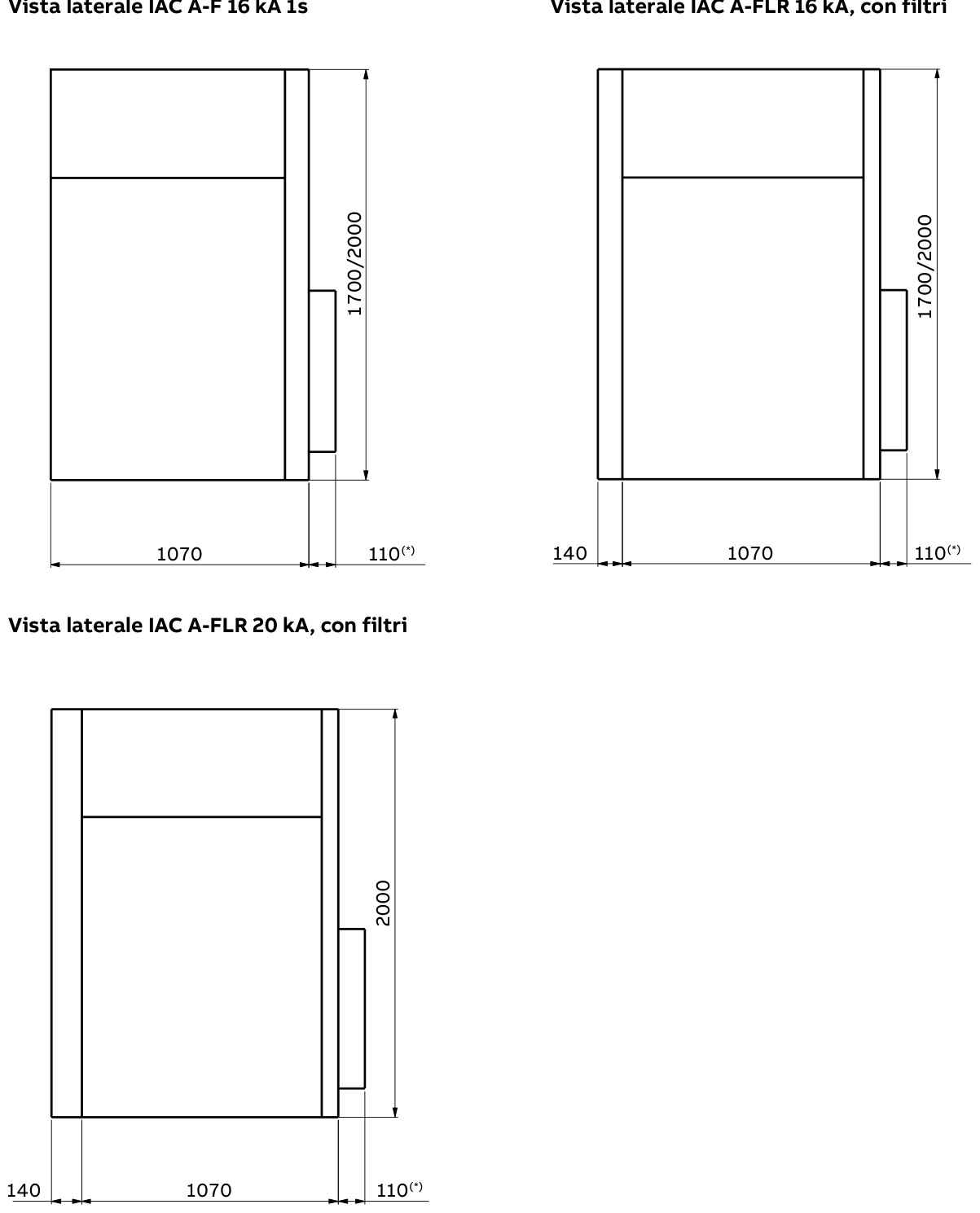
Side view · with filters.
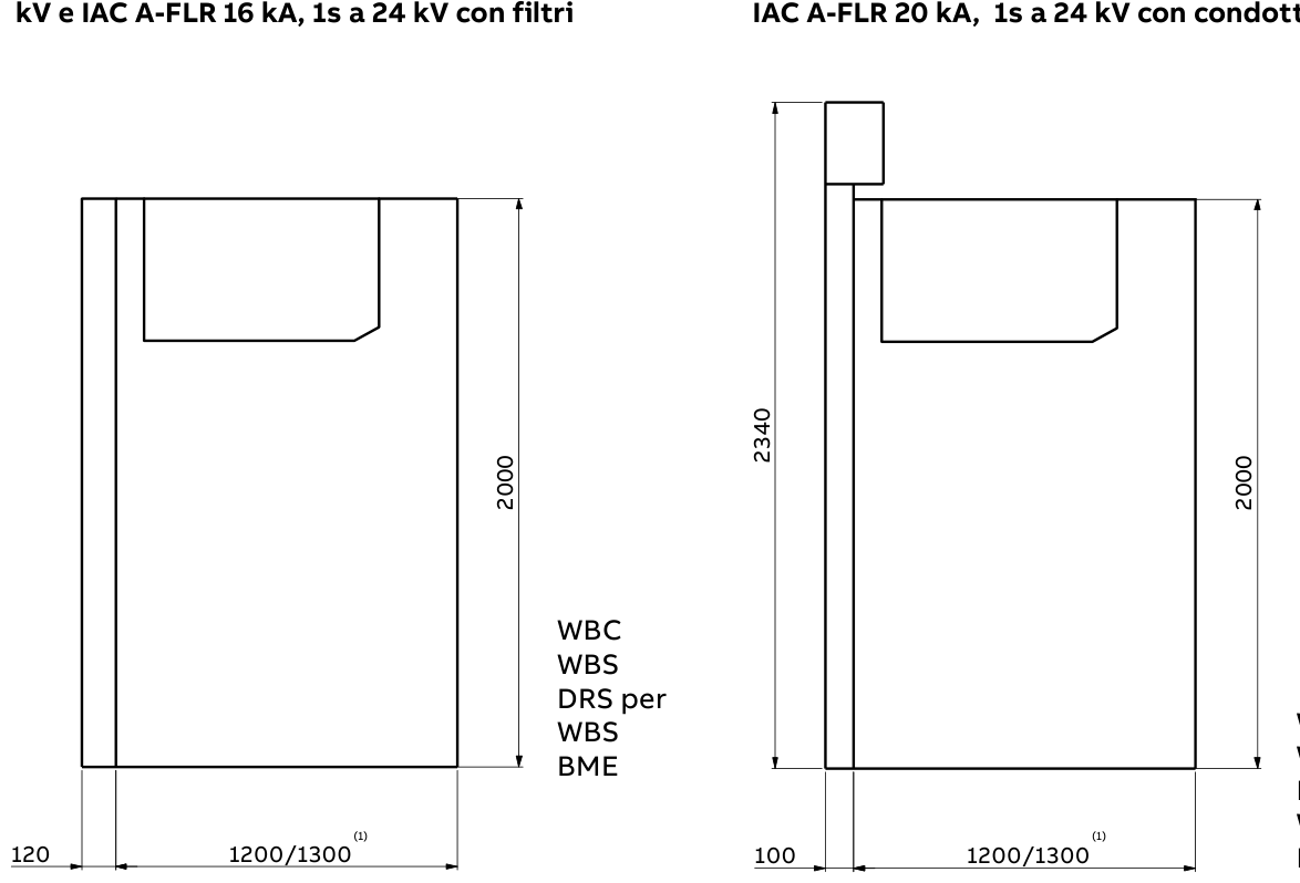
With filters · with an exhaust duct · DRS for WBS.
Low-voltage compartments
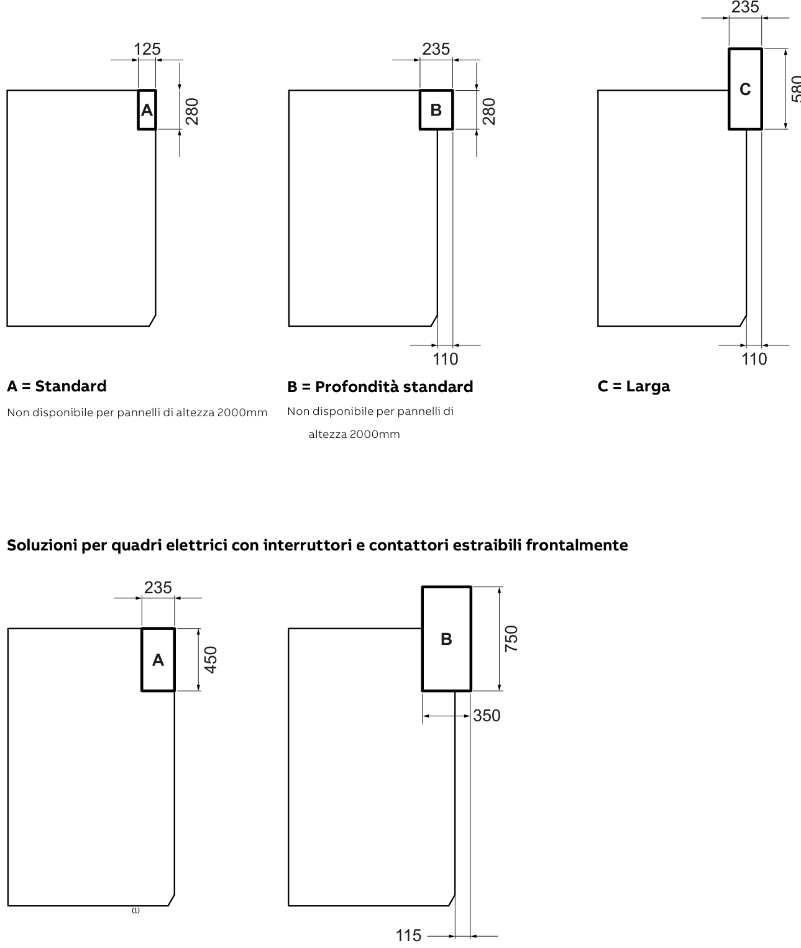
B = Standard depth. C = Wide. Not available for 2,000 mm-high panels. Solutions for switchgear with front-withdrawable circuit-breakers and contactors.
Larger LV compartments
Scroll to view all columns ↔| Unit | LV compartment type | Depth [mm] | Height [mm] | Front projection [mm] |
|---|---|---|---|---|
| With switch-disconnector or disconnector | C – Large | 235 | 580 | 110 |
| With withdrawable circuit-breaker/contactor | B – Large | 350 | 750 | 115 |
Indicative weights of base units, for heights of 1700 / 2000 mm, with 630 A main busbars and without components (CTs, VTs, surge arresters, fuses, etc.).
Base-unit weights · schedule 1
Scroll to view all columns ↔| Width [mm] | SDC | SFC | SBC | SBS | SFV | SBR |
|---|---|---|---|---|---|---|
| 500 | 170/180 | 175/185 | – | – | 175/185 | – |
| 750 | 195/210 | 200/215 | 335/355 | 355/375 | – | 335/355 |
Base-unit weights · schedule 2
Scroll to view all columns ↔| Width [mm] | DRC | DRS | DRS | SFC | SFV | DRC | SDS |
|---|---|---|---|---|---|---|---|
| 500 | 135/145 | 140/150 | 160 | 225 | 225 | 270 | 180 |
| 750 | – | – | – | – | – | – | – |
Indicative component weights
Component weights
Scroll to view all columns ↔| Component | Weight |
|---|---|
| DIN CT 12/17,5 kV | 22 kg |
| DIN CT 24 kV | 33 kg |
| DIN VT 12/17,5 kV | 20 kg |
| DIN VT 24 kV | 35 kg |
| Set of three fuses | 19 kg |
| VD4/R-Sec circuit-breaker | 90 kg |
| VD4/Sec, VD4/P circuit-breaker | 125 kg |
| VSC/P contactor (excluding fuses) | 52 kg |
| Airsec disconnector | 38 kg |
Gas-exhaust system weights
Scroll to view all columns ↔| Gas exhaust system | Unit width | H 1700 mm | H 2000 mm |
|---|---|---|---|
| Duct | 750 mm | 30 kg | 45 kg |
| Filter | 500 mm | 34 kg | 41 kg |
| Filter | 750 mm | 47 kg | 54 / 72 kg (1) |
Note. The dimensions and weights shown are indicative and may vary depending on the final supply configuration and installation conditions. They are not binding: the reference values are those in ICEL’s project drawings and documentation.
For your project. Weights are transcribed from the catalogue schedules. Some summary and unit-sheet values differ: for example DRS 135/145 and 140/150 kg; SBR 355/375 and 335/355 kg. Repeated DRC/DRS columns do not identify the variant. Use project drawings for engineering.
The room must be prepared according to the switchgear dimensions and version. Observing the stated clearances ensures correct and safe operation. For different conditions, contact the ICEL technical department.
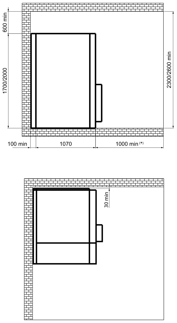
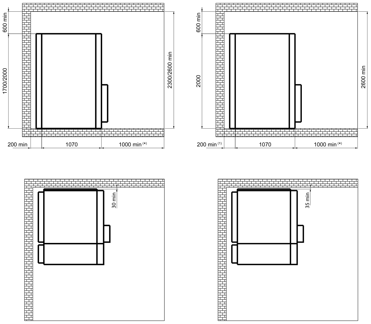
Minimum room clearances [mm]
Scroll to view all columns ↔| Configuration | Rear clearance | Switchgear depth | Front aisle | Between switchgear and side wall | Space above switchgear | Minimum room height |
|---|---|---|---|---|---|---|
| LSC2A – IAC A-F 16 kA (base) | 100 | 1070 | 1000 (*) | 30 | 600 | 2300 / 2600 |
| LSC2A – IAC A-FLR 16 kA, filters | 200 | 1070 | 1000 (*) | 30 | 600 | 2300 / 2600 |
| LSC2A – IAC A-FLR 20 kA, filters (H 2000) | 200 | 1070 | 1000 (*) | 35 | 600 | 2600 |
Minimum values in mm. (*) At least 1300 mm with circuit-breaker units, or 1030 mm with the optional special trolley (VD4/R-Sec only). LSC2B depth: 1200 mm at 12–17,5 kV, 1300 mm at 24 kV.
Cable entry and fixing
Cable-entry openings below the units must be made before the switchgear is installed. Each unit has one fixing point at each corner (4 per unit); 10 mm anchor bolts can be used. The dimensions and positions of fixings for units without cable entry depend on the width.
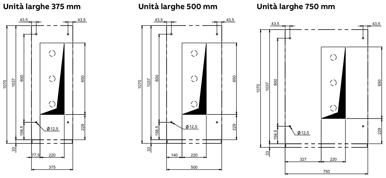
Units 375 / 500 / 750 mm wide.
375, 500 and 750 mm LSC2A units
LSC2A unit footprint
Scroll to view all columns ↔| Unit | Width [mm] | Overall depth [mm] |
|---|---|---|
| LSC2A (375 / 500 / 750) | 375 / 500 / 750 | 1070 |
Foundations
The switchgear must be installed on a base with a flatness of 2 mm per metre along the switchboard and sufficient load capacity for its weight. It can be anchored to a concrete floor, a metal frame or a raised floor.
The cable connection height, measured between the connection point and the floor, depends on the unit and installed accessories.
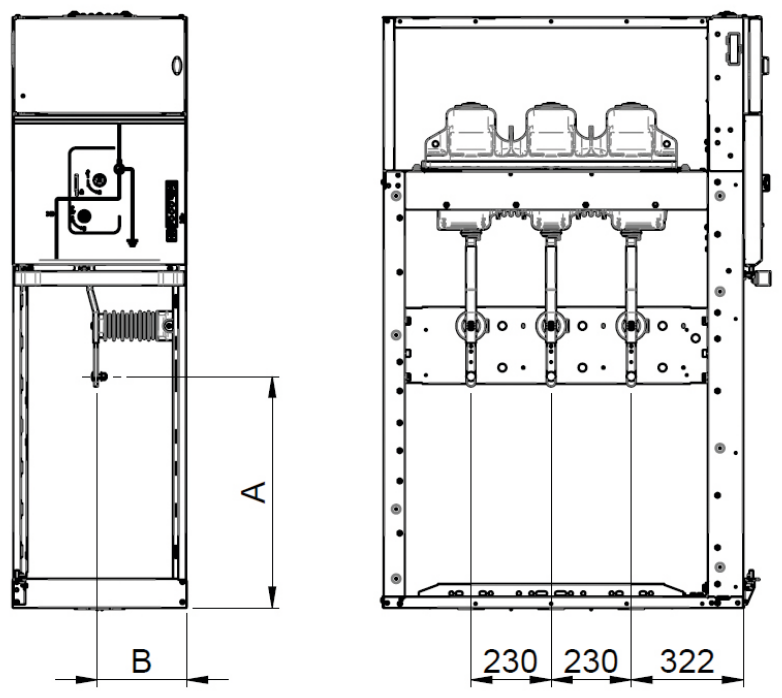
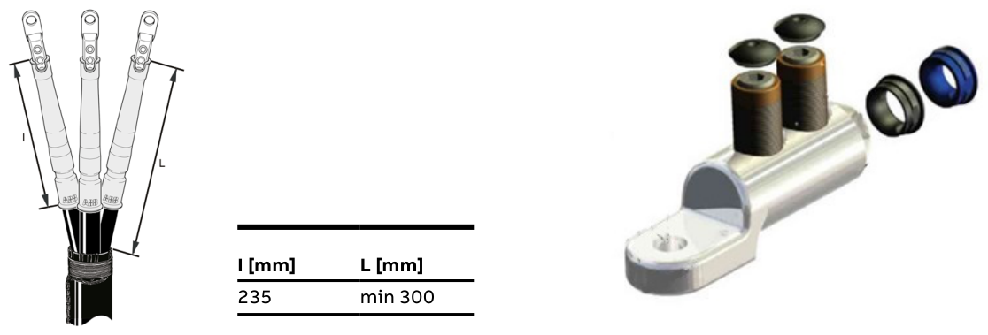
Cable connection dimensions A and B [mm]
Scroll to view all columns ↔| Unit | 190 – A | 190 – B | 375 – A | 375 – B | 500 – A | 500 – B | 600 – A | 600 – B | 750 – A | 750 – B |
|---|---|---|---|---|---|---|---|---|---|---|
| SDC | – | – | – | – | 665 | 275 | – | – | – | – |
| SDC with CTs | – | – | – | – | 530 | 275 | – | – | 530 | 265 |
| SFC with 292 mm fuse | – | – | – | – | 600 | 240 | – | – | 570 | 400 |
| SFC with 442 mm fuse | – | – | – | – | 450 | 240 | – | – | 570 | 400 |
| SBC | – | – | – | – | – | – | – | – | 610 | 355 |
| SBC with CTs | – | – | – | – | – | – | – | – | 480 | 340 |
| DRC | – | – | – | – | 670 | 240 | – | – | – | – |
| DRC with CTs | – | – | – | – | 530 | 275 | – | – | – | – |
| DLR | – | – | 1280 | 210 | – | – | – | – | – | – |
| SBR | – | – | – | – | – | – | – | – | 400 | 390 |
| SDS | – | – | – | – | 530 | 275 | – | – | – | – |
| RLC/RRC H1700 | 1495 | 310 | – | – | – | – | – | – | – | – |
Dimensions in mm; headers = unit width – dimension. (1) Distance between the side of the unit and the first cable connection. Phase-to-phase connection pitch (LSC2A units): 235 mm, minimum free length 300 mm.
Maximum cable number and cross-section
Maximum cable count and cross-section
Scroll to view all columns ↔| Unit | Width [mm] | Max. cables per phase | Max. cross-section [mm²] |
|---|---|---|---|
| SDC | 500 | 1 / 2 | 240 / 240 |
| SFC | 500 | 1 | 150 |
| SBC | 750 | 2 | 240 |
| DRC | 500 | 1 / 2 | 240 / 240 |
| SBR | 750 | 2 | 240 |
| RLC – RRC | 190 | 1 | 240 |
For your project. RLC/RRC unit sheets list a 200 mm width, while cable tables list 190 mm. The connection drawing shows 230/230 mm phase spacing and the text states 235 mm. Original values are retained: confirm dimensions against the project drawings.
06 / TECHNICAL ANSWERS
YOUR PROJECT.
MADE CLEARER.
When should I choose LHS UniSec Air for secondary MV distribution?
It is ICEL’s air-insulated, SF6-free solution for secondary medium-voltage distribution. The LHS UniSec Air catalogue describes a modular 12, 17.5 and 24 kV range, with incoming, outgoing, protection, metering and riser units.
How do I select voltage, current and short-circuit ratings for LHS UniSec Air?
Ratings depend on voltage and unit. The LSC2A switching units described are rated 630 A, with short-time withstand up to 20 kA for 3 s; DLR and RLC/RRC are listed at 16 kA for 3 s. The general table also includes 1,250 A and 25 kA versions: 25 kA applies at 12 and 17.5 kV, not at 24 kV. The combination must be defined for the project.
Is LHS UniSec Air SF6-free medium-voltage switchgear?
The switchgear’s live parts are air-insulated. GSec Air uses dry air as its insulating medium, with a GWP of zero, and dedicated vacuum interrupters for load breaking. Insulation and interruption are separate functions.
Which units are available?
The catalogue describes DRC, DRS, DLR, SDC, SFC, SFV, SBC, SBS, SBR, RLC/RRC and SDS. Each unit sheet includes its application, technical data, standard equipment and optional accessories.
Which ABB apparatus is described in the catalogue?
LHS UniSec Air is part of ICEL’s MV range using licensed ABB technology. The catalogue describes apparatus including the GSec Air switch-disconnector and VD4/R-Sec vacuum circuit-breaker. Apparatus, accessories and combinations depend on the individual functional unit.
Is the internal arc classification the same for every version?
No. The base version is listed as IAC AF up to 16 kA for 1 s. Versions with filters or an exhaust duct reach IAC AFLR 20 kA for 1 s; 25 kA for 1 s is listed only for LSC2B units up to 17.5 kV. Switchgear configuration, gas exhaust and room layout must be assessed together.
Can LHS UniSec Air integrate sensors and digital monitoring?
Yes. The catalogue lists current and voltage sensors, combined sensors and protection relays according to the selected unit. The range is designed for integration with digital monitoring systems. Required devices, signals and interfaces must be defined for the project: monitoring is not an identical standard package for every panel.
What information is needed for a quotation?
A single-line diagram, rated voltage and current, short-circuit level, required functions, cable data and room constraints. Attach your documentation to the form: ICEL will help define the technical solution. Final dimensions and configurations are governed by the project drawings.
Data and illustrations are indicative and non-binding. ICEL may change them as the products evolve. Project drawings and documentation govern. Component photographs: ABB; technical illustrations: ICEL LHS UniSec Air 2026 catalogue.
YOUR NEXT PROJECT STARTS HERE
LET’S GIVE
YOUR IDEAS
POWER.
A project to develop, a partnership to propose or a question to ask. Let’s start here.
01 / Tell us what you need
02 / Share the relevant documents
03 / Let’s define the solution